+86 15093323284 hams@ailunce.com


The Basic Information of Yagi Antenna
The importand of the antenna.
As an electromagnetic transducer element, the position of the antenna in the entire radio communication system is very important. The quality directly affects the distance and effect of the transmission and reception. In other words, there is no radio communication without the antenna.

What's the Yagi antenna?
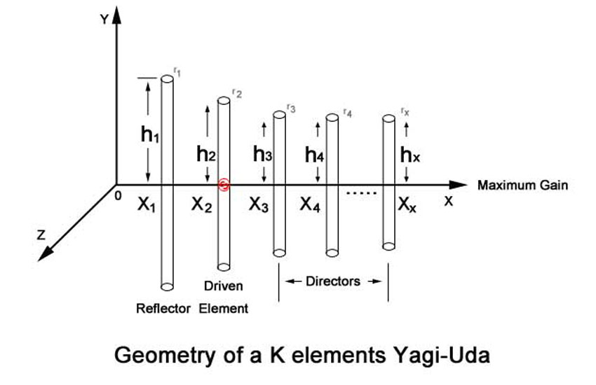
A Yagi–Uda antenna, commonly known as a Yagi antenna, is a directional antenna consisting of multiple parallel elements in a line, usually half-wave dipoles made of metal rods. Yagi–Uda antennas consist of a single driven element connected to the transmitter or receiver with a transmission line, and additional "parasitic elements" which are not connected to the transmitter or receiver: a so-called reflector and one or more directors.

The advantage of the Yagi antenna.
Compared with the basic half-wave symmetric vibrator or the folded vibrator antenna, Yagi antenna has high gain, strong directivity, anti-interference, and long distance, and has a simple structure, easy material availability, low price, small windshield surface, lightweight and firmness, and convenient erection. Usually, the Yagi antenna consists of an excitation oscillator (also called the main oscillator), a reflection oscillator (also called a reflector), and a number of directors (also called directors).

In contrast, the reflector is the longest and is located next to the main. On one side of the vibrator, the director is short, and all of them are located on the other side of the main vibrator. The number of all the vibrators is the number of units of the antenna. For example, a five-unit Yagi antenna includes a main vibrator and a Reflector and three directors. The main vibrator is directly connected to the feeding system and belongs to the active vibrator. The reflector and the director are passive vibrators. All the vibrators are in the same plane and are fixed in parallel at a certain distance to a metal traversing the center of each vibrator. On the beam.

For the design of an antenna, we always hope that it can have higher efficiency and gain, sufficient bandwidth, and strong signal selection and anti-interference ability, while matching the feeder impedance as much as possible, trying to reduce the standing wave ratio and reduce Signal loss. However, the geometric parameters of the antenna have an influence on its electrical performance, and often contradict each other and contain each other.

When design adjustment, you can't ignore this. You must combine the actual use and comprehensive consideration, distinguish the primary and secondary, and sacrifice some minor if necessary. Performance. Since the gain of the Yagi antenna is closely related to the axial length (distance from the reflector to the last director), the number of cells, the length of the vibrator and the spacing, the longer the axial direction, the more the number of cells is actually the direction, the more the direction. The sharper the sharper, the higher the gain, the farther the range is, but after more than four directors, the improvement effect is less obvious, while the volume, weight, and manufacturing cost are greatly increased, and the material strength requirements are also stricter, resulting in The working frequency band is narrower.

In general, it is sufficient to use 6 ~ 12 units, and the antenna gain can reach 10~15 dB. For high gain requirements, the antenna array can be used to solve the problem. The length of the director is usually (0.41~0.46) λ. The more the number of cells, the shorter the optimal length of the director. If the working frequency band is required to be wide, the length of the director should be shorter. The distance between the directors is generally (0.15~0.4) λ. After greater than 0.4λ, the antenna gain will drop rapidly, but the distance between the first director B and the main oscillator should be slightly smaller than other spacings, for example, when b≈0.1λ, The gain will increase.

Since the director array has effects on gain, back radiation, input impedance, etc., the experimental adjustment is an indispensable step before the Yagi antenna is put into use. When debugging, be sure to frame the antenna and leave the ground at a height of two or three meters to avoid affecting the impedance and elevation angle of the antenna. When the Yagi antenna is set up, the antenna plane where the vibrator is located can be parallel to the earth or vertical.

As long as the antennas of both the receiving and transmitting sides maintain the same posture, the horizontally polarized waves are radiated in parallel, and the vertically polarized waves are radiated in the vertical direction. The isolation can also be set up with two pairs of mutually perpendicular guiding antennas, which is very convenient to use. In order to avoid a more complicated phase relationship and reduce the difficulty of adjustment, the plane of the vibrator is usually perpendicular to the beam. Because the length of each vibrator is about half a wavelength, the midpoint of the vibrator is located at the zero points of the voltage of the electric wave induction signal, so the midpoint of the vibrator can be directly fixed by metal bolts and aluminum beams, without insulation, so that it can easily discharge the induction.

Static electricity. If the main vibrator uses a half-wave symmetry vibrator, the place where the feeder is connected must be well insulated from the beam. If a half-wave folded vibrator is used, the midpoint is still connected to the beam. The metal beam is perpendicular to the direction of polarization of the electric field in the direction of the end-fire and therefore does not have a significant effect on the radiation field of the antenna. In addition, it should be noted that since the antenna is generally installed in an outdoor environment such as a roof or a balcony, the interface is easily oxidized and rusted by the wind, the sun is exposed to the rain, and the signal transmission and the antenna matching are affected, so that the transmission and reception effects are deteriorated. The waterproof tape should be treated in advance, and lightning protection should also be noted.